| Station Setup |
| 2300-A8VI |
Station Summary
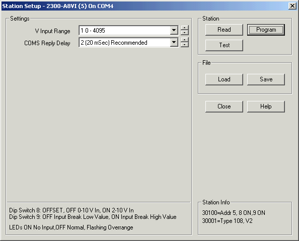
Station Programming dialog

After changes are made, click "Program" to write changes to station.
Settings Table
| V Input Range | 1 0 - 4095 (Recommended Setting) 2 0 - 10.000V 3 +/- 10.000V 4 0 - 1.000V 5 +/- 1.000V |
| Reply Delay | 0 to 990 mSec (20 mSec recommended) |
DIP Switch Table
| Switch 1-7 | Address (See Address Table) |
| Switch 8 | Offset OFF = No Offset ON = Input 2-10V |
| Switch 9 | Sensor Break OFF = Input Break = Low Value ON = Input Break = High Value |
| Switch 10 | No Action, Leave OFF |
LED Indications
| 1-8 INPUT LED OFF | Input Normal |
| 1-8 INPUT LED ON | Input Faulty |
| 1-8 INPUT LED FLASHING | Input Overrange |
| P | Flashing - Station is Powered up and working |
| R | Flashes to indicate good modbus message arrived for this station |
| T | Flashes to indicate reply message has been sent from this station |
Station Info (Read from station)
| 30100 | Dip Switch settings |
| 30001 | Station Type and Software Version (Type = 108) |
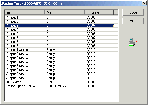
Station Test Dialog

The V Input values are shown as 0 - 4095
Status shown as Healthy or Faulty.
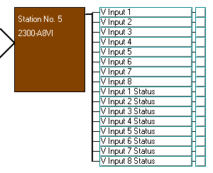
Station Map Display
