| Station Setup |
| 2300-RTD6 |
Station Summary
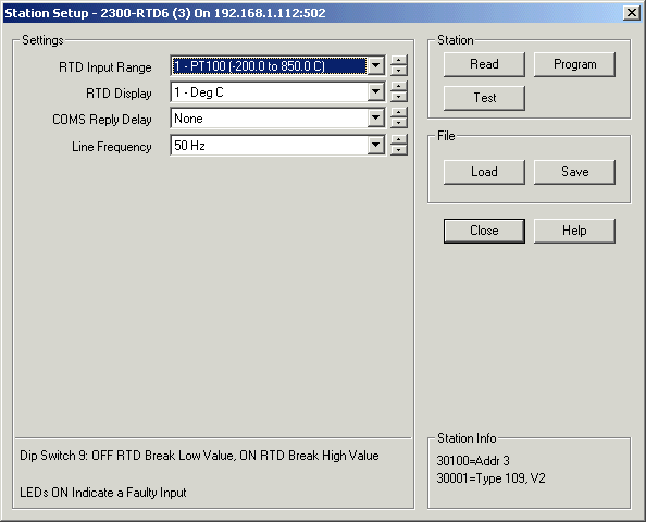
Station Programming dialog

After changes are made, click "Program" to write changes to station.
Settings Table
| RTD Input Range | 1 - PT100 (-200.0 to 850.0 C) 2 - Ni120 (-80.0 to 230.0 C) 3 - PT1000 (-200.0 to 850.0 C) 4 - Ni1000-DIN (-200.0 to 850.0 C) 5 - Ni1000-Landys&Gyr (-200 to 850.0 C) 6 - Ohms 10-400 (10.00-400.00) * 7 - Ohms 100-4000 (100.0-4000.0) * |
| RTD Display | 1 - Deg C 2 - Deg F |
| COMS Reply Delay | 0 to 990 mSec (20 mSec recommended) |
| Line Frequency | 50 Hz 60 Hz |
* Must be read into tags and scaled by a tag.
DIP Switch Settings
| Switch 1-7 | Address (See Address Table) |
| Switch 8 | No Action, Leave OFF |
| Switch 9 | Sensor Break - OFF = RTD break = low value ON = RTD break = high value |
| Switch 10 | No Action, Leave OFF |
LED Indications
| 1,2,3,4,5,6 INPUT LED OFF | Input Normal |
| 1,2,3,4,5,6 INPUT LED ON | Input Faulty |
| P | Flashing - Station is Powered up and working |
| R | Flashes to indicate good modbus message arrived for this station |
| T | Flashes to indicate reply message has been sent from this station |
Station Info (Read from station)
| 30100 | Dip Switch settings |
| 30001 | Station Type and Software Version (Type = 109) |
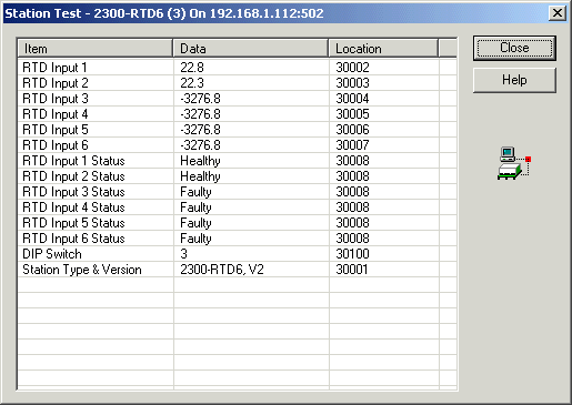
Station Test Dialog:

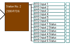
Station Map Display

NOTE: For using Psuedo Digital inputs into a RTD6, Select the input range 1 - PT100 (-200.0 to 850.0 C), and the Sensor break must be ON, so that when the input contact is open, the RTD will read a high value.
Alternatively, the RTD Input Status can be used, for a good RTD reading "Healthy" will be returned and for a bad RTD reading "Faulty" will be returned.
Error checking can be provided by reading the RTD Input X Status value from the station as a digital, this is 1 (Healthy) when the RTD is reading OK, and 0 (faulty) when the probe is in error.