| Help Topics |
| Demo Setup Modbus RTU |
This demo shows the connection to a Modbus PLC via Modbus RTU (serial connection).
| Equipment Needed | Settings |
| Serial Modbus PLC | Unit Number 1, 9600,n,8,1 on COM1 |
| Data at 30001,30002,30003 |
Summary of Steps:
Settings - Select Tag Module and PLC Interface in Select Module Wizard
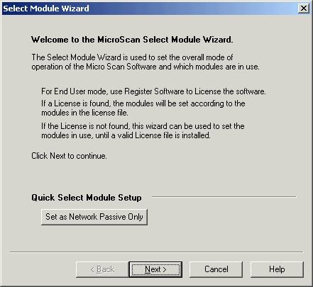
On Setup Tools, click Select Module Wizard

Click Next
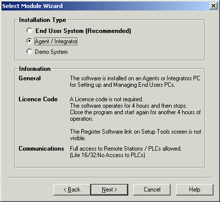
Select Agent Mode, Click Next
Note for this demo, the Agent Mode is used but on a real job, End User System
would be used with a dongle.
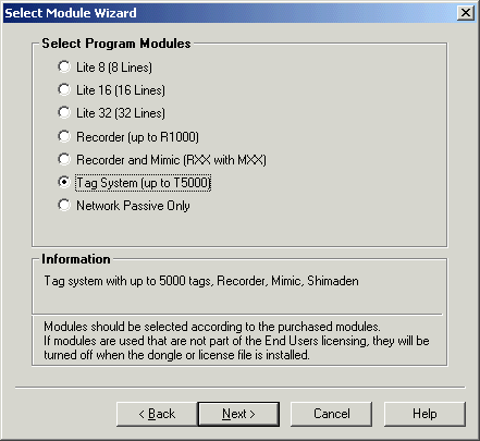
Select Tag System, click Next
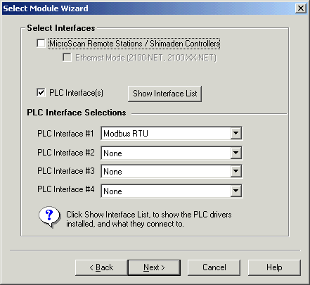
Click PLC Interfaces ON, select PLC Interface #1 as Modbus RTU, click MocrScan Interface Off, click Next.
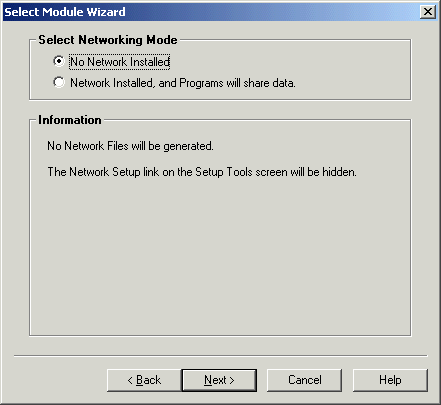
Click Next
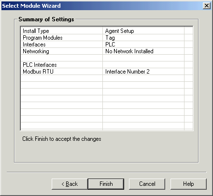
Click Finish
Settings - Setup PLC Interface Settings
On Setup Tools, click PLC Interface link
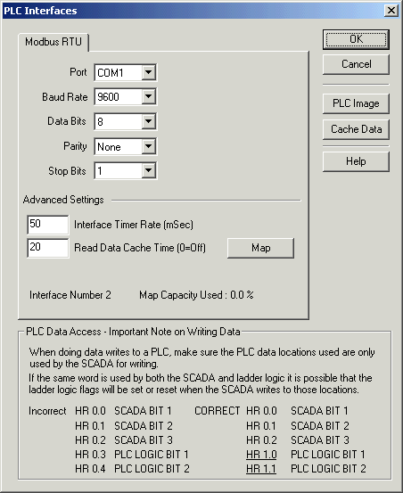
Select Port to COM1, click OK.
Note: Do not use the Map dialog on this window to setup PLC details up - this is
done automatically when tags and lines are edited in Version 5.
Settings - Set Tag to access PLC locations
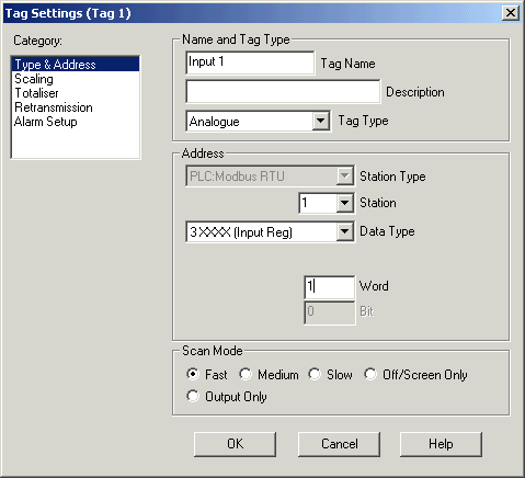
Setup for Input 1, at address 30001
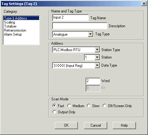
Setup for Input 2, at address 30002
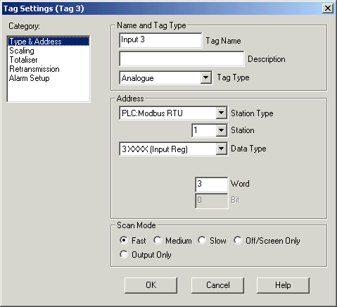
Supported Data Locations
| Location | Read Command | Write Command |
| 0xxxx (coils) | 0x01 | 0x05 |
| 1xxxx (input) | 0x02 | N/A (read only) |
| 3xxxx (input register) | 0x04 | N/A (read only) |
| 4xxxx (holding register) | 0x03 | 0x06 |
Note on Modbus Locations:
The MicroScan tag dialogs allow you to enter an address such as Input Reg
Word 1, that would actually be 30001.
But some PLC documentation gives the addresses in terms of the modbus protocol
which is all zero referenced (i.e starts at zero) - so when you enter a modbus
address, one may need to be added to counter for this value.- If 30001 is
entered in the dialog, it actually means that Input Register 0 is being sent out
in the protocol message. For A16 products a modbus address is given such as
30001, 30002 and these are the values that should actually be used.