| Help Topics |
| Demo Setup Omron FINS |
The Omron FINS driver is used to communicate with OMRON ETN21 Ethernet units.
Key Features:
The ETN21 will support up to 16 simultaneous socket
connections.
The MicroScan can talk to the unit, at the same time as CX Programmer.
For each ETN21 a MicroScan computer will open a socket to the ETN21 and leave it
open.
The MicroScan driver uses FINS messages, and no other software such as FINS
gateway needs to be installed on the computer.
Comms speed is 10-15 times faster than serial comms.
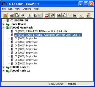
IO Table for ETN21 in PLC
NOTE: Changes To ETN21 setup require the PLC to be
RESTARTED
ETN21 Setup
Unit No.
Set to a free number for the unit in the PLC rack.
Node No x16(0) and x16(1)
Set to the same value as will be used as the ip address
of the unit.
IE
This same setting MUST be in the ETN21 setup dialogs as shown below.
Status LEDs
ERC, ERH These
are normally OFF.
Any ON or flashing activity indicates a fault see tables in ETN21 documentation.
SD
TCP
LNK On to
indicate good ethernet signal.
NOTE:
The ETN21 is added to the PLC in the ETN21 Mode, not
the ETN11 mode.
The ETN21 dialog should look as below.
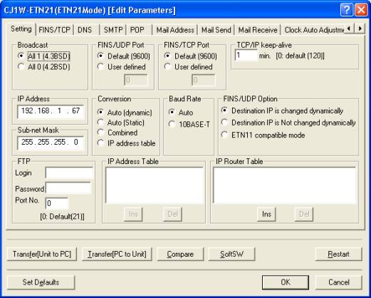
Key settings needed
IP Address
Set to the IP Address of the unit (192.168.1.67 in this case) the 192.168.1.XXX
XXX value must match that of the Node number switches in the unit.
Sub Net address
Normally set to 255.255.255.0
TCP/IP Keep alive time
Set to a suitable value (1 or 5 mins) so that the PLC will timeout the socket
and allow reconnect if network issues are detected.
Default setting of 0 Not Recommended as it will mean a
timeout time of 2 hours in case of bad networking connections and sockets can't
be connected.
Default Settings kept - No Changes required
FINS/UDP port
Default 9600
FINS/TCP port
Default 9600
Conversion
Auto (dynamic)
Transfer the settings and Restart the PLC for the ETN21
to start using them.
No other settings or PLC programs are required for the
MicroScan to connect to the ETN21 unit, The settings shown in the dialog above
are those used to test microScan to ETN21. If in any doubt, set your ETN21
settings to be the same. No changes are required to any other Tab settings pages
in this dialog.
Testing
Use a command prompt and ping XXX.XXX.XXX.XXX to test
that the network connection and ip setting is correct.
Check the RUN light is ON
Check that both the ERC and ERH lights are OFF.
Check that the LNK light is ON.
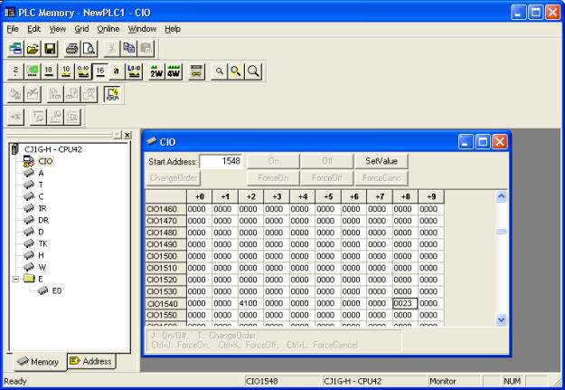
Monitoring Microscan Socket Connnections in the PLC
Socket connections can be monitored by looking at word
CIO 1500+25 x Unit Number and look at n+23. Each bit On indicates a socket
connected. The other status info in CIO table for the ETN21 is not relevant to
Microscan as it pertains to using networking with PLC ladder logic instructions.
i.e for Node 1, this would be CIO 1500+25*1+23 = CIO
word 1548.