| Setup MicroScan |
| Line Setup: Digital Display Detail |
This window gives summary information on a digital lines settings.
You can make changes to the settings and then visit this dialog, to confirm the settings will give the result you need.
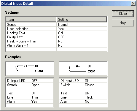
Digital Input on 2100-A16: Normal Input

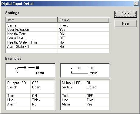
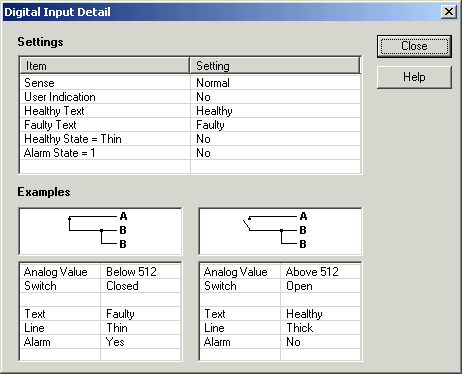
The Examples shows the following.
| DI Input LED | Shows the state of the LED on the station ON = LED ON. OFF = LED OFF. |
| Switch | Shows the position of the switch in the graphic Open = Switch Open Closed = Switch Closed |
| Text | Shows the text shown on the data screen Shows either Healthy or Faulty or the user defined text |
| Line | Shows the size of the line on the line graph Thin = Thin line drawn Thick = Thick Line drawn |
| Alarm | Shows if the alarm is active Yes = the value is an alarm condition No = the value is not an alarm condition |
| Link Alarms | Shows if the alarms on the lines using this line as a link
alarm will be monitored. Active = The alarms will be monitored Not Active = The alarms will not be monitored (Will show as Yellow on Data Screen). |
Digital Input on 2100-A16: Inverted Input

Psuedo Digital Input on 2100-A16: Normal Input
