| ZigBee Wireless Data Links | |
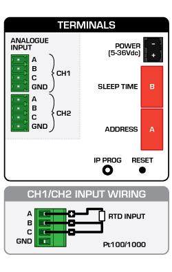
| Setup Input Connections & Ranging |
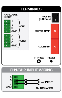
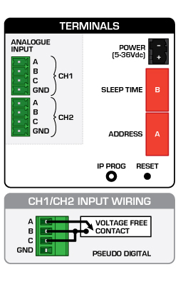
Input Connection Diagrams for sleeper
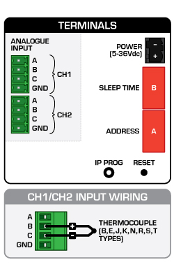
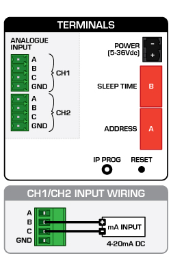
| RTD (Scaled 0.1 C/0.1 F) | TC (Scaled 0.1C/0.1 F) | mA (0-20 mA = 0-100 % or 4-20mA = 0-100 %) |
|
|
|
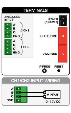
| V (0-10V = 0-100 %) | mV (0-100mV = 0-100 %) | PD |
|
|
|
For 4-20 mA inputs connected to the sleeper please see the following restriction:
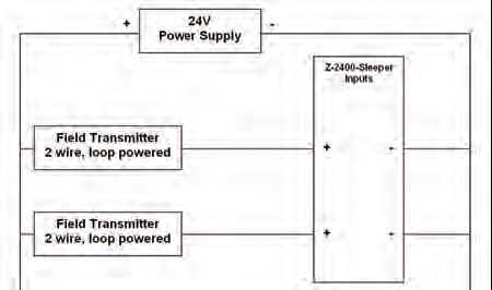 |
1. The two analogue inputs are not isolated from each other, and care must be taken when connecting signals that are not isolated from each other or ground.2. Both analogue signals can share a common as per this example 3. If permanently powering the Z-2400-Sleeper, use only an isolated power supply eg isolated from ground and other devices. Do not use this power supply to power external devices. If only a common power supply is available, use the PSW-2 isolating power supply to power the Sleeper only to maintain isolation.4. The current loop will be broken when the sleeper is sleeping. For failsafe current operation on a current loop shared with other displays or input devices the sleepers internal mA links must be installed. |
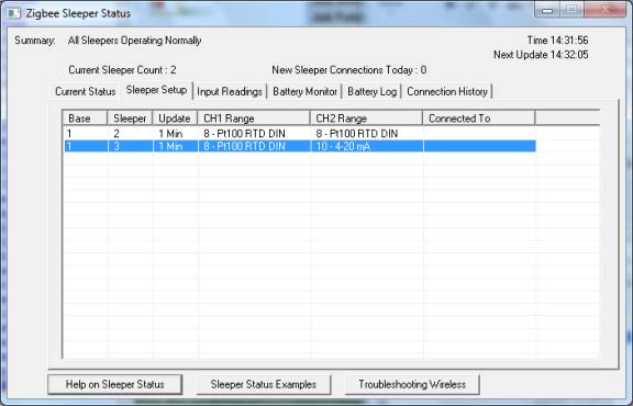
Sleeper Line Ranging in MicroScan
In order to setup lines to read from sleeper inputs, the base + sleeper must be working properly, so the scaling information for each input can be transferred.
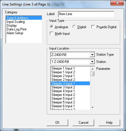
For the example setup, sleeper 3, CH1=RTD, CH2=4-20 mA
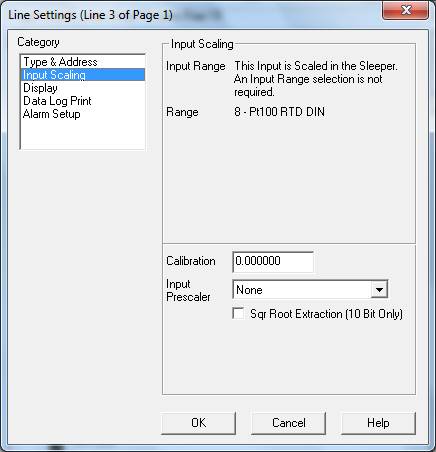
Sleeper scaling when input is CH 1 RTD/TC
Type & Address
Input Scaling
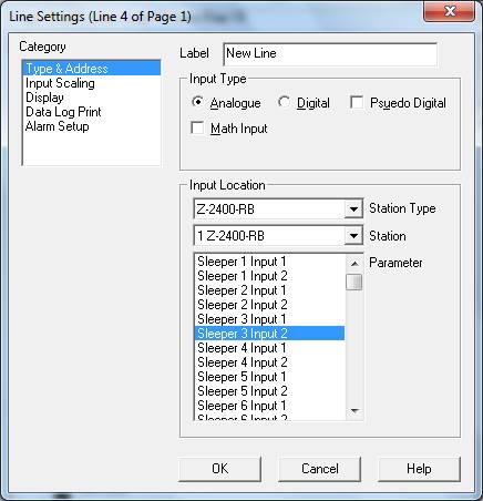
Sleeper scaling when input is CH2 DC input
Type & Address
Input Scaling
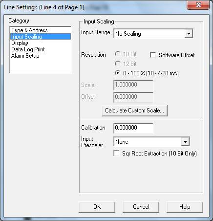
You will see 0-100 % (10 4-20 mA) indicating the range that the sleeper channel is set to.