| Station Setup |
| 2300-MULTI |
Station Summary
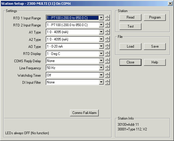
Station Programming dialog

After changes are made, click "Program" to write changes to station.
Settings Table
| RTD 1 Input Range RTD 2 Input Range |
1 - PT100 (-200.0 to 850.0 C) 2 - Ni120 (-80.0 to 230.0 C) 3 - PT1000 (-200.0 to 850.0 C) 4 - Ni1000-DIN (-200.0 to 850.0 C) 5 - Ni1000-Landys&Gyr (-200 to 850.0 C) 6 - Ohms 10-400 (10.00-400.00) * 7 - Ohms 100-4000 (100.0-4000.0) * |
| A1 Type A2 Type |
1 0 - 4095 (mA) Recommended for mA Input 2 0 - 20.00mA 3 +/- 20.000mA 4 0 - 4095 (V) Recommended for V Input 5 0 - 10.000V 6 +/- 10.000V 7 0 - 1.000V 8 +/- 1.000V |
| AO Type | 1 - 0-20 mA 2 - 0-10 V |
| RTD Display | 1 - Deg C 2 - Deg F |
| COMS Reply Delay | 0 to 990 mSec (20 mSec recommended) |
| Line Frequency | 50 Hz 60 Hz |
| Watchdog Timer | Off to 255 Seconds The relays will turn OFF if no comms commands are received after this time limit expires. If set to Off, watchdog function does not operate. |
| DI Input Filter | None 1 (10 mSec) to 999 (9990 mSec) Use to filter out noise on DI signals. If set to too high a value will reduce frequency of inputs that can be read. |
Comms Fail Alarm
For more information, see 2300 Comms Fail Alarm
DIP Switch Table
| Switch 1-7 | Address (See Address Table) |
| Switch 8 | No Action, Leave OFF |
| Switch 9 | No Action, Leave OFF |
| Switch 10 | No Action, Leave OFF |
LED Indications
| All other LEDs OFF | |
| P | Flashing - Station is Powered up and working |
| R | Flashes to indicate good modbus message arrived for this station |
| T | Flashes to indicate reply message has been sent from this station |
Station Info (Read from station)
| 30100 | Dip Switch settings |
| 30001 | Station Type and Software Version (Type = 112) |
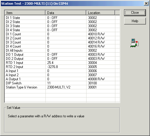
Station Test Dialog

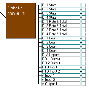
Station Map Display

Note : Use DI Rate & Total for counter input rate and totaliser
information into lines and tags
Psuedo Digital Inputs cannot be Used on RTD 1 and 2 inputs on a 2300-MULTI.