| Setup MicroScan |
| Line Setup: Connect to PLC |
Programmable Logic Controllers (PLCs).
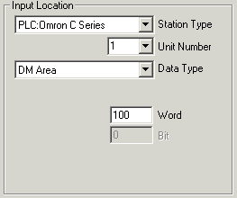
Example Input Location when connecting to a PLC.

When a line is connected to a PLC, the Setup Program keeps track of which plc locations have been allocated. This information is used to build the PLC Map display on the Right Hand Side of the Main Editing Window.
Connecting a Line to a PLC location.
Select the PLC type from Station Type. When the PLC is chosen, the contents of the Input Location will change reflecting the type of PLC and the data areas that can be accessed within that PLC.
In this example, an Omron PLC is being accessed.
If the line is set as Analogue, the "Bit" field will be grayed. If the line is Digital, the bit field will be available for use.
The text next to Unit Number changes according to the type of PLC, or may not be there if the PLC does not need an address number.
If the line is connecting to an Allen Bradley PLC, a File Number field is visible below the Data Type as each data area is specified with a file number.
When the lines setup has been entered by pressing the OK button, the PLC Map on the right of the Main Editing Window will be changed to show the Bit or word location being accessed within the PLC.
See Also