| Setup MicroScan |
| Line Setup: Input Scaling |
The Input Scaling Category is used to set up the scaling details for a line.

This category applies to Analogue Input Lines connected to an outstation or PLC. It determines how an analogue input will be scaled.
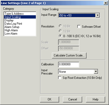
Input Range
If a 2100-XX direct input is being used such as RTD or TC input, these inputs are already scaled in the outstation. A scaling values do not need to be applied here.
The Input Range gives a list of commonly used input ranges. Select the range required to match the range of the input transducer or if the line is connected to an EXPO3R//2100-M, the range of the expander. ALL lines connected to an expander MUST be scaled to match the range of that expander.
If the range is not in the list, See the section Calculate Custom Scale below to enter a custom range.
For reading of parameters out of Shimaden Controllers, set the Input Range to No Input Scaling.
When a Input Range is selected, the Scale and Offset edit controls below are automatically calculated to reflect the scale values required to convert the input to this range.
NOTE: If the Input Range is set to "No Recorder Scanning", the recorder will not scan this line, and it expects data to be put into the line via a DDE Command. Also when you switch back to the Type & Address Category, the Input Location will show "No Address Required as the Input Range is set to No Recorder Scanning".
Resolution
10 Bit
12 Bit
0-100
%.
This is the accuracy of the input. It is determined by the
type of hardware that the input signal is connected to. For the IN2000-AI
modules, it is always 10 Bit. For a 2100-M or EXPO-3R, connected to a 2100-A16,
this will be 12 Bit.
For a 4-20 mA or other DC signal signal connected to a 2100-A16 Input 1-16, this
will be 0-100 %.
Software Offset
The software offset is turned on when a 4-20 mA input is connected to a 0-20 mA input. (Used on old IN2000-XX only)
Scale
This value is the scale factor used to convert the input range to the required real value.
Offset
This value is a constant used to calculate the real value from the raw input.
If the Input Range is set to Custom Scale, the following formula is used
Line Reading = (rawinput * scale) + offset + calibration
Calibration
The calibration value is added to the lines input value after the input has been scaled. It is used to fine tune the input to the correct value in conjunction with a known input reference. To decrease the value of the input, specify a negative calibration value. Online calibration is possible via the Recorder's calibration box. See Calibrate Lines.
Input Prescaler
This is an input function that can be used to apply a formula to the input of the line before it is scaled. The actual prescaler functions are contained in FILTER32.DLL and are custom written to perform prescaling on input lines. Current Prescaler functions are shown in Prescaler Functions.
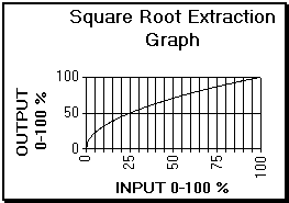
Square Root Extraction
The Square Root Checkbox is used to apply a square root extraction formula to the input. This should only be used or 10-bit inputs (IN2000 - AI) or otherwise it will give incorrect results.

See Also
Type & Address
Input Scaling
Display
Data Log Print
Alarm Setup
High Alarm
Low Alarm
Digital Display
Digital Alarm
Math Settings
Tag Scaling
Counter Scaling