| Setup MicroScan |
| Line Setup: High Alarm |
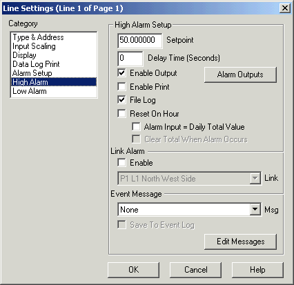
The High Alarm Setup Category is used to setup the High Alarm Settings for a
line.
For further information on Recorder Alarms, see Recorder
Alarm Operation.

Setpoint
This is the figure which the alarm must be above (for the high alarm) or below (for the low alarm) if the alarm is to be flagged.
Delay Time (Seconds)
This is the time in seconds, that the input must be exceed the setpoints before the alarm is activated.
Enable Output
When selected, this allows the alarm relays setup to be turned on or off
when the alarm is flagged.
Click "Alarm Outputs" to setup the up to four relay outputs for
this alarm.
See Line Alarm Outputs.
Enable Print
When set, a printout occurs when
the alarm is flagged. The output is set to the printer set by the printer output
selection Printer 1 or Printer 2, See Line
Setup, Alarm. The logging printer is set on Graphics
& Logging Printers.
When set, the alarm messages are logged in a file which can be examined using
the Alarm Log accessible from the log display on the
Navigation Tree.
File Log needs to be on if the Alarm
Log Comment mode is used, so that a comment entered when the alarm is
cleared can be saved to the correct alarm entry in the alarm log.
Reset On Hour
If this is set and the alarm is still outside of limits on the hour the alarm
will be reflagged and reprinted. This occurs the selected time interval after
the alarm occurs. See Alarm
Settings, Auto Reset Time.
Alarm Input = Day Total Value
When set, the high setpoint is compared to the Daily Total Value instead of the
lines current value.
For High Alarm Settings Only.
Clear Total When Alarm Occurs
If this is set, the daily total is cleared when an alarm occurs. This is used
only when the Daily Total is used for the alarm generation rather that the lines
current value.
For High Alarm Settings Only.
Link Alarm
This feature enables the use of a digital input to inhibit the action of the
alarms on this line. If the digital input specified by the Page and Line is
Healthy (state = 1) the alarm will be enabled, if it is Faulty (state =
0) the alarm will not be enabled. When the Link input makes the
transition from faulty to healthy, the alarm timers are reset to zero for the
line, thus giving the input the "Delay Time" to return within limits
before the alarm is flagged. To engage the link alarm, click the Enable checkbox
on, and select the digital line to do the link control from the Link combo box.
When a lines alarm is disabled via a link, it will be drawn in yellow on the Recorders Data Screen.
Note: An analogue lines value can be used to control the link, as long as the value is ZERO for alarm not monitored and NON ZERO for alarm monitored. For Example, a low cut off could be used on a level transmitter to enable the monitoring of an alarm above the low cut off value (when the tank is bwing used), and not monitor it below the cut off value (when the tank is empty).
See Alarm Operation, Link Alarm for more information.
Event Message
The Event Message is used to record a canned message when the alarm occurs
rather than the recorders standard alarm message. The Event Messages are setup
by clicking on the Edit Messages button. To select an event message choose
one from the Msg combo box. To cause the event message to appear in the
Recorder's Event Window click "Save To Event Log" on. You can edit the
Messages by clicking the Edit Messages button.
Edit Messages
Click Edit Messages to edit the Event Messages, See Edit
Event Messages.
After you edit messages the Msg combo box will be refreshed with the new
messages entered.
See Also
Type & Address
Input Scaling
Display
Data Log Print
Alarm Setup
High Alarm
Low Alarm
Digital Display
Digital Alarm
Math Settings
Tag Scaling
Counter Scaling